Simple Tips About What Are The Three 3 Types Of Schematic Diagram

Schematic Diagram Symbols Chart Circuit
Understanding Schematic Diagrams
1. What Exactly Is a Schematic Diagram?
Ever felt lost trying to assemble IKEA furniture with those cryptic instructions? Well, imagine tackling electronics without a proper map! That's where schematic diagrams come in. Think of them as blueprints for electronic circuits, using symbols and lines to show how components are connected. Theyre not pretty pictures of the actual parts (that's more like a layout diagram), but rather a simplified, logical representation of how everything talks to each other. It's like the difference between a map of the subway system (schematic) and a photograph of the tracks (layout). One tells you where to go, the other shows you what it looks like.
Schematic diagrams are essential for anyone working with electronics, from hobbyists tinkering in their garages to professional engineers designing complex systems. They help you understand how a circuit works, troubleshoot problems, and even design your own circuits from scratch. Without them, you'd be poking around blindly, hoping for the best. And lets be honest, hoping is rarely a good strategy when dealing with electricity! They provide clarity and a standard language for discussing and documenting electronic designs. This makes collaboration much easier and reduces the chance of miscommunication. After all, nobody wants to accidentally fry their project because they misinterpreted a connection.
Why are these diagrams important, you ask? Because they offer a birds-eye view of the entire circuit, allowing you to trace signals, identify critical components, and understand the overall flow of electricity. It's like having a GPS for your electronic project, guiding you through the maze of wires and components. They also play a crucial role in documentation. A well-drawn schematic makes it easy for others (or even your future self!) to understand and maintain the circuit. Imagine trying to fix something you built a year ago without any documentation a schematic saves you time, effort, and potential headaches. In short, schematics are the unsung heroes of the electronics world.
Now, before you start picturing complex mazes of wires and symbols, let's break down the three main types of schematic diagrams. Don't worry, it's not as intimidating as it sounds. We'll make it simple and straightforward, with a dash of humor thrown in for good measure. After all, learning should be fun, even when dealing with electrons!

Schematics And Diagrams
The Big Three
2. 1. Block Diagrams
Think of a block diagram as the executive summary of a circuit. It shows the major functional units (or "blocks") of a system and how they relate to each other. These blocks could represent anything from amplifiers and filters to microcontrollers and sensors. The focus is on the overall flow of signals and data, rather than the specific components or connections within each block. It's like looking at a map of the country, showing major cities and highways, without getting bogged down in the details of every backroad.
Block diagrams are often used in the early stages of design to plan out the system architecture. They help engineers visualize the big picture and identify potential bottlenecks or areas for improvement. Imagine trying to build a house without a floor plan you'd end up with a chaotic mess! Block diagrams serve a similar purpose in electronics, providing a roadmap for the design process. They are also useful for communicating complex systems to non-technical audiences. Instead of getting lost in a sea of transistors and resistors, stakeholders can quickly grasp the overall functionality and purpose of the system. It's a great way to impress your boss (or your grandma) without overwhelming them with technical jargon.
The beauty of a block diagram lies in its simplicity. It allows you to focus on the essential elements of a system without getting distracted by the intricate details. This is especially helpful when dealing with complex systems that involve multiple subsystems. By breaking the system down into manageable blocks, you can analyze each part separately and then see how they all fit together. It's like tackling a giant puzzle you start by sorting the pieces into smaller groups before trying to assemble the whole thing. Block diagrams provide that initial organization and clarity, making the design process much more manageable.
So, if you ever find yourself staring at a blank canvas, wondering where to start, remember the block diagram. It's the perfect tool for mapping out the overall structure of your project and ensuring that all the pieces fit together harmoniously. And who knows, you might even impress your friends with your newfound ability to explain complex electronics in simple, easy-to-understand terms!
3. 2. Ladder Diagrams
Ladder diagrams are the language of Programmable Logic Controllers (PLCs). PLCs are like the brains behind many industrial automation systems, controlling everything from conveyor belts to robotic arms. Ladder diagrams provide a visual way to program these PLCs, representing logical operations in a format that resembles a ladder. Each rung of the ladder represents a logical condition, and the PLC executes these rungs sequentially to control the output devices. It's like following a recipe each step (or rung) tells the PLC what to do next.
Think of it as a series of switches and relays arranged in a logical pattern. The "rails" on either side of the ladder represent the power supply, and the rungs contain the logic that controls the outputs. Inputs, such as sensors and pushbuttons, are represented by switches, while outputs, such as motors and lights, are represented by relays or coils. By connecting these elements in different ways, you can create complex control sequences. It's a bit like building a Rube Goldberg machine, but with electrical components instead of marbles and dominoes.
Ladder diagrams are widely used in industrial automation because they are easy to understand and debug. Even someone without a deep understanding of electronics can often follow the logic of a ladder diagram and identify potential problems. This makes it easier for maintenance technicians to troubleshoot and repair PLC-controlled systems. They also offer a standardized way to represent PLC programs, making it easier for engineers to collaborate and share code. It ensures that everyone is speaking the same language, regardless of their background or experience.
While ladder diagrams might seem a bit niche compared to other types of schematics, they are essential for anyone working with industrial automation. They provide a powerful and intuitive way to program PLCs and control complex machinery. So, if you're looking to automate your factory or build your own robot army (for purely educational purposes, of course), ladder diagrams are a skill worth learning.
4. 3. Electronic Schematic Diagrams
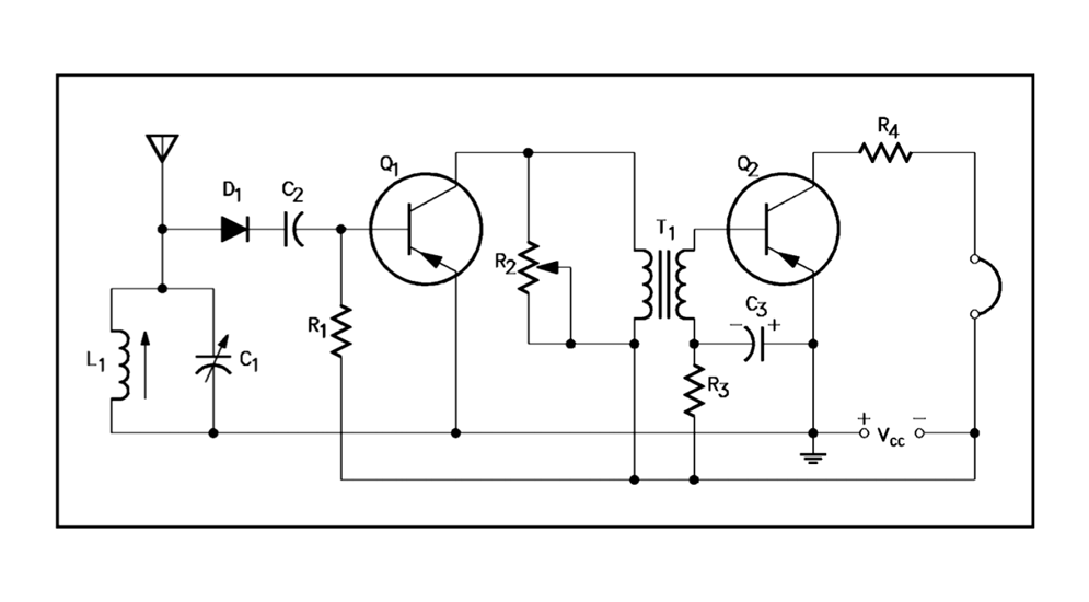
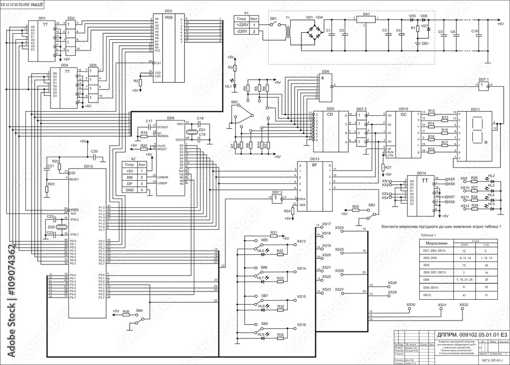
This is probably what pops into your head when someone says "schematic diagram." An electronic schematic diagram shows all the individual components in a circuit (resistors, capacitors, transistors, ICs, etc.) and how they are connected together. These diagrams use standardized symbols to represent each component, making it easy to identify them and understand their function. It's like having a detailed map of the circuit, showing every street, building, and landmark.
These schematics are used for everything from designing simple circuits to troubleshooting complex electronic devices. They provide a complete and accurate representation of the circuit's electrical connections, allowing engineers to analyze its behavior and identify potential problems. Imagine trying to diagnose a faulty computer without a schematic diagram you'd be poking around blindly, hoping to stumble upon the problem. A schematic provides a clear roadmap, guiding you through the intricate network of components and connections.
Electronic schematic diagrams are the workhorses of the electronics industry. They're used in everything from product design and manufacturing to repair and maintenance. They're essential for communicating designs, troubleshooting problems, and ensuring that circuits are built correctly. A well-drawn schematic is a thing of beauty, a testament to the power of human ingenuity and the elegance of electronic design. Plus, they look really cool when framed and hung on your wall. (Okay, maybe not, but they are pretty important!)
To truly understand an electronic circuit, you have to be able to read and interpret its schematic diagram. It's like learning a new language once you master the basic symbols and conventions, you can unlock a whole new world of knowledge and understanding. So, grab a pencil, a piece of paper, and a schematic diagram, and start exploring the fascinating world of electronics!

Why Knowing These Schematics Matters
Knowing the different types of schematic diagrams isn't just about impressing your nerdy friends (although, that's a definite bonus). It's about being able to effectively communicate and collaborate in the world of electronics. Imagine trying to explain your circuit design to someone using only words it would be a confusing and frustrating experience for everyone involved. Schematic diagrams provide a common language, allowing you to share your ideas with clarity and precision. Think of it as the Esperanto of electronics.
Furthermore, understanding these diagrams is crucial for troubleshooting and repairing electronic devices. When something goes wrong, a schematic diagram can help you trace the flow of signals and identify the source of the problem. It's like being a detective, following the clues to solve the mystery of the malfunctioning circuit. Without a schematic, you're essentially working blind, relying on guesswork and luck. And as any seasoned electronics enthusiast knows, luck is a fickle mistress.
Beyond the practical applications, learning about schematic diagrams can also be incredibly rewarding. It's like gaining access to a secret code, unlocking the inner workings of the electronic devices that surround us. You'll start to see the world in a whole new light, appreciating the ingenuity and complexity of the technology we often take for granted. It's a journey of discovery that can lead to a deeper understanding of the world and your place in it. (Okay, maybe that's a bit dramatic, but it's still pretty cool!).
So, whether you're a seasoned engineer or a curious hobbyist, take the time to learn about the different types of schematic diagrams. It's an investment that will pay off in countless ways, both personally and professionally. And who knows, you might even discover a hidden talent for electronic design, leading to a fulfilling and rewarding career. The possibilities are endless!

The Key Distinctions Wiring Diagram Vs. Schematic
FAQ
5. Q
A: Absolutely not! While a formal education in electrical engineering can certainly be helpful, anyone can learn to read and interpret schematic diagrams with a little bit of effort and practice. There are plenty of resources available online and in libraries that can guide you through the basics. Start with simple circuits and gradually work your way up to more complex ones. And don't be afraid to ask for help the electronics community is generally very supportive and willing to share their knowledge.
6. Q
A: One common mistake is confusing schematic diagrams with layout diagrams. Remember, schematics show the logical connections between components, while layouts show their physical arrangement. Another mistake is failing to pay attention to the component symbols. Each symbol represents a specific type of component, and understanding these symbols is essential for interpreting the diagram correctly. Finally, be sure to double-check your connections and polarities. A simple mistake can lead to a short circuit or a damaged component.
7. Q
A: Finding schematic diagrams for commercial electronic devices can sometimes be a challenge, as manufacturers often keep them confidential. However, there are several online resources that may be helpful. Websites like datasheets.com and alltransistors.com provide datasheets for various electronic components, which often include example circuits. You can also try searching online forums and communities dedicated to electronics repair and hacking. Sometimes, members of these communities will have schematics that they're willing to share. And who knows, you might even find a treasure trove of information lurking in the depths of the internet. Just be careful not to download anything from untrusted sources!

